FSQ-106N Electronics Build
This is a combination of multiple projects and provides an overview of what it took to bring them all together to create my setup.
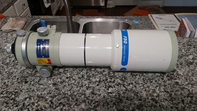
A while back, I found a great deal on a Takahashi FSQ-106N. It's not the latest version of the series, but that doesn't mean that it can't perform just as well as the others. While it can't use a reducer, I concluded that to increase my field-of-view, I would instead get a larger sensor when the opportunity arises. I also came to the justification, based on other reviews, that if anything, it should produce better star colors and the focuser is better than newer ones. Once I bit the bullet and made the purchase, I immediately began planning how I would build my electronics control panel for it, similar to my build for the LXD75.
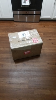
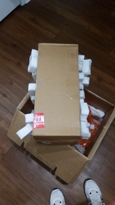
Woohoo, it's here!
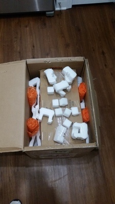
I received the scope in the mail, and the first order of business was to check everything out to make sure it was safe and in good condition.
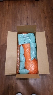
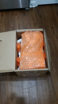
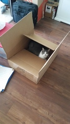
and of course, my trusty sidekick Riley had to inspect the shipments as well.
After feeling confident that everything was in order, and as expected, the process and plans I put together commenced!
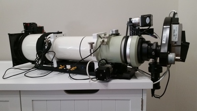
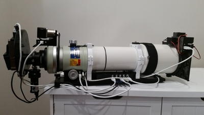
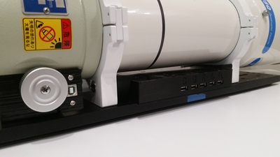
Just like with the LXD75 build, my goal was to incorporate a group of electronics to control the primary imaging camera, guider, focuser, dew controller, and a couple of new goodies, a rotator, and calibration cover. Through the use of a powered USB hub, the goal was to combine everything; however, unlike the last build, I wanted to mount everything under the scope instead of on top. Doing so would not only make the setup look cleaner, but also lower the center of gravity to give the mount a slight advantage by reducing the torque needed to move the scope around the night sky. Also, it gives me the option to place something else on top in the future. I broke out my trusty digital caliper and started taking measurements to compare against my initial design, and at first, I had lost faith that my plan would be feasible. I only had 30 mm of space under the scope, and taking into account the size and number of electronics needed, spacing, and temperatures, I wasn't sure it would be possible to tuck everything beautifully underneath. However, after drawing up some design changes and utilizing 3D CAD software, I felt confident I could make it work. So I moved forward with the five parts of my designs, starting at the rear of the scope, tackling the easy stuff first, and working my way ahead to the new ideas.
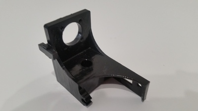
Part 1: The focuser
Instead of reinventing the wheel, as with my other scope, I decided to implement Robert Browns' myFocuserPro software which has been tried and true for me. At this part of the build, all that was necessary was to design a bracket to support the motor. However, instead of creating something that has to be attached somewhere to the scope or the dovetail, I found it was easy enough to remove the existing cover from the focuser and replace it with a single 3D printed part. Doing so would that not only covered the gear but also allowed me to mount the motor and run the wiring. After four hours of printing on my Monoprice Maker Select V2 and a quick vapor smoothing shower, the piece was ready to be installed and the necessary hardware attached.
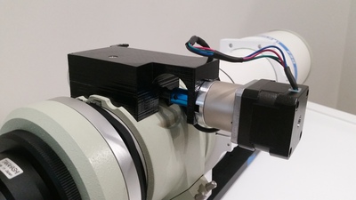
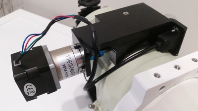
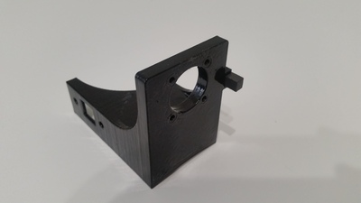
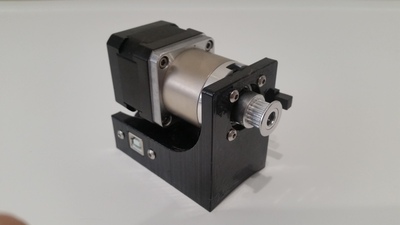
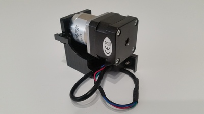
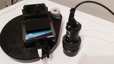
Part 2: The rotator
With the first part complete, I was able to move forward to my favorite part of the build and a new challenge. The new scope offered me a feature I previously didn't have, the ability to rotate the camera and frame objects at different angles. The benefit of this allows me to do it without requiring me to manually adjust the camera within the drawtube, which could throw my alignment out or some other unknown issue. I found that someone named Kevin from scopefocus.info created something similar, but unfortunately his solution was not fully going to work for me. After some initial testing, I learned that my back focus would not be as far as I had expected. Instead, it was very close to the focuser, which didn't provide much clearance, and the way I was going to mount the motor, it wouldn't have the room for 360 degrees of rotation. I was able to solve this problem in two parts. The first part was also an easy task, designing a bracket to hold the motor, a plug-in for the USB, and a magnet for homing the rotator, which only took a little over two hours to print.
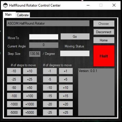
The second part was quite easy as well, after some initial studying. A few days were spent understanding the concepts of ASCOM and designing the software and driver, but after a few tests, I'd like to introduce you to the HalfRound Rotator! This is a full-functioning, ASCOM compliant program, that provides 360-degree positions all within the confines of 180 degrees of movement. More details about designing the software, interface, and necessary parts can be found here.
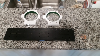
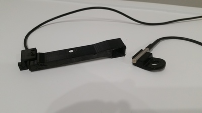
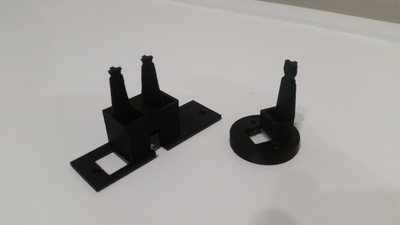
Part 3: Cable management
With the back of the scope built, in conjunction with the rotator, I became concerned about how the cables may dangle and move as the rotator switched positions. To ensure that wires don't snag or rip out of the equipment, I decided to design brackets that would provide secure connections and also keep the cables close to the dovetail. The top two pictures show two brackets. The bracket on the right holds a temperature sensor that is mounted on top and used for the focuser. The other bracket (on the left) was designed to mount onto the dovetail, which holds a hall sensor for homing the rotator, and allow the camera cables to stay close to the dovetail. The bottom photos are brackets that connect to the cameras to support the USB and power cable.
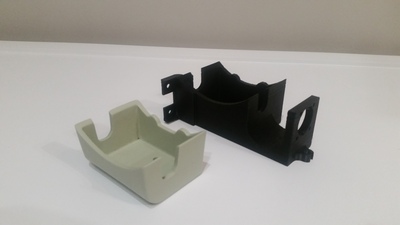
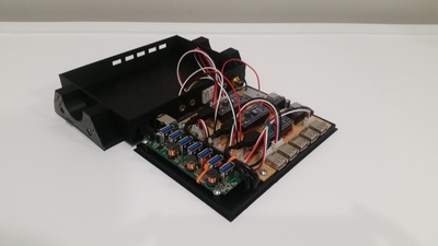
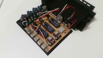
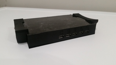
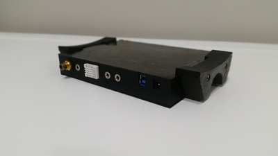
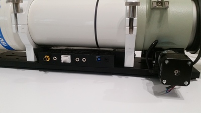
Part 4: The HUB
At this point, I was halfway through the build, and this was the main event. I wanted to create something that would hold a 7-port USB hub and 3 Arduinos to control a dew controller, focuser motor, and rotator motor. My intent was not only to combine everything into a simple design, but a system that would be protected from dew, hold a sensor for dew control and allow all cables to be plugged into a central location. This is the final result of what I was able to create and the details of this build can be found here.
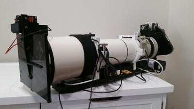
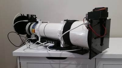
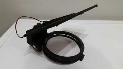
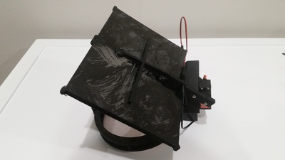
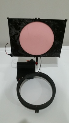
Part 5: The cover and calibrator
We've reached the last part of the build and the goal here was to create something similar to Optec's Altinak Flip-Flat Flat Fielder, but without the high cost. Being remote, I needed a way to protect the objective when not in use, while also having the ability to take calibration frames after a night of imaging. After a few tests and modification, the following design allows me to remotely open/close the cover and also adjust the brightness level of an Electroluminescent (EL) Panel. More details about designing the software, interface, and necessary parts can be found here.
The final product
That's it! All of that work went into developing these items now allow me to have full remote control functionality from anywhere around the world. I am excited to get first light in my new scope and see how it performs, especially with the larger FOV.