HalfRound Rotator (HRR) Build
In case you hadn't read the overview page about the entire FSQ-106N build, the new scope offers me a feature I previously didn't have; the ability to rotate the camera and capture objects at different angles. This is important because it means I don't have to manually adjust the camera within the drawtube, which could throw my alignment out or some other unknown issue. Also, it's extra special because I'm remote and can't easily make the change unless I go for a long drive. Before I began to build this part of the project, I did some research and found others who also built a version of a rotator, and one, in particular, was very close to what I needed. I had found someone on scopefocus.info, but unfortunately their solution was not going to work for me. However, I could still use the same design principles and have the motor rotate around a GT2 belt, and unbeknownst to me this project would require me to solve the problems in two parts.
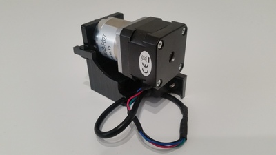
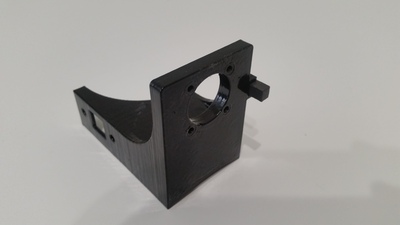
The first issue was the hardware. The parts I found were designed for a different size scope, and this meant I had to come up with my design. After taking a few measurements of the focuser tube, I calculated the correct number of teeth for the pulley and began 3D printing the first part. It took a couple of iterations to get tight tolerances to prevent any shift in the pulley, but once I was comfortable with the fit I moved onto designing motor mount.
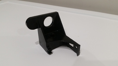
In addition to rotating, one additional feature I wanted to incorporate was a homing sensor that way I could reset my position to a known location, and due to obvious reasons of the system being outside, I wanted to use parts that would be as weatherproof as possible. I decided to use a hall sensor and magnet and wanted to embed the magnet in the bracket. I also attempted to make the design as simple as possible and built the bracket without the need for a belt tensioner. Only time will tell if it holds up or if I need to go back and redesign the bracket, but for now, also after a couple of iterations, I was able to get the height correct that once bolted into place the motor since firmly on the rotator and maintains tight tension against the belt.
This is the first design I settled on.
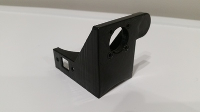
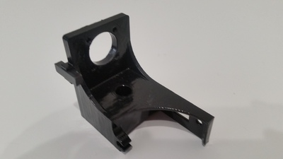
However, after some additional thought and since I haven't had the ability to real-world test my design I became concerned that if the focuser moved either in or out to far, the homing sensor may not function. This led me to redesign the bracket and use a different magnet that would allow further movement of the focuser without losing the ability to home.
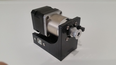
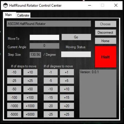
The second part to solving the problem was where the real fun was at. All current rotators provide 360 degrees of rotation and must be designed to prevent cords getting wrapped up, but after some initial testing I learned that my backfocus would not be as far as I had expected. This became an issue because of the way the motor was mounted. It wouldn't provide enough clearance for 360 degrees of rotation and I had to come up with solution to work within the limits of 180 degrees of movement. Also, a side benefit of the limited movement meant I didn't have to worry about cord wrap situations. After understandings the concept of ASCOM I began to design and code a full functioning, ASCOM compliant program called the (HRR) HalfRound Rotator.