Hub Build
The hub build was by far the most stressful part of the build. Not because there was anything complicated about the design or implementation, I knew I could easily mount the electronics on top of the scope, but as the development progressed my idea came into question. With this setup, I wanted to tuck the electronics under the scope for two reasons. The first reason was that I felt it would look better. The second reason was in an attempt to keep the center of gravity as low as possible, regardless of how light the parts may already be being 3D printed.
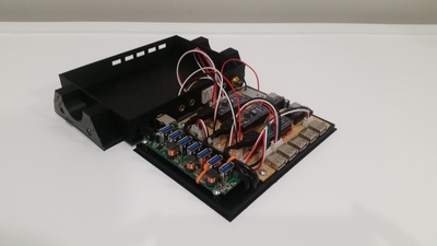
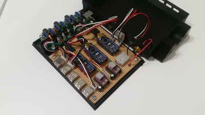
When I first began my design, I measured the height of the Arduinos, USB powered hub, and space in between the dovetail and the scope. Initially, I felt confident that everything would fit under the scope; however, one issue became apparent and that was the length between the two scope rings. My 3D printer has a maximum legnth of 200mm to print and the distance between the two rings was at minimum 230mm. The best part about 3D printing is the possabilties, so I knew the size wasn't necessarily a problem, it only meant I would have to come up with an innovative solution to "bridge the gap," so to speak, to find a solution for mounting my design. Undeterred, I moved to CAD software and began tackle the design and layout the components.
Orginially, I planned to mount four Arduino Nanos inside, each one to control a different feature; focuser, rotator, dew controller, and flip-flat. Unfortunately along the way, due to the size constraints, it left very little room for everything and to overcome this concern, I ultimately chose to move one Arduino in with the electronics for my flip-flat.
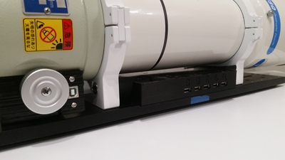
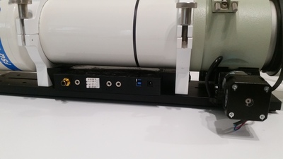
Overall, the first iteration was a success. It did fit under the scope, but I felt it was a tight fit, so with a little tweaking, I was able to lower the overall height and ready to move forward. At this point, before I printed the second and hopefully final version, I shifted my attention to designing a solution to mount the hub. I could have easily used a couple screws and moounted the hub to the dovetail, but since I haven't been able to put the scope on the mount, I was concerned that I may have to potentially shift the position of the scope on the dovetail and if this was the case, the mounting holes for the hub may not align. After looking over the hub, scope, and rings, I noticed the rings had two holes and that I could print a couple of brackets with embedded nuts and sandwhich the hub in betwee them. With a couple of test prints of the brackets, I was able to finalize a design that snapped into the hub to create one part and then screw the whole assembly to the rings.
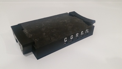
After adding the new brackets and a succesful second test fit, the only thing left to do was paint the recessed lettering to consider this project complete.
 <
<