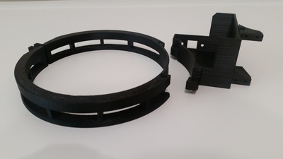
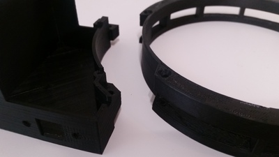
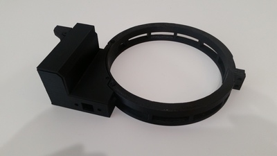
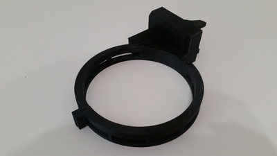
DarkLight Cover Calibrator (DLC) Build
This project was one of the easier projects to undertake but still required creative solutions to develop the final product I had envisioned. As many are aware, Optec's Altinak Flip-Flat Flat Fielder is pretty much the only commercial option out there that provides a motorized calibration panel that doubles as a cover. Unfortunately, it appears that, like most companies, they would rather sell a few at a higher profit instead of a lot at a lower price. At the starting price of $535, I was unwilling to pay that amount, especially when I knew I could create an identical item at a much lower price. Many of us have used some kind of illuminated panel for our calibration frames; I use one for my other scope. The issue, though, with the larger scope is that I have no way to cover the scope when I'm done for the night, leaving the front exposed to dust, bugs, spiders, and birds, oh my! This post does have photos of the final design, but I didn't take many pictures of each iteration I went through, so this will be more of an explanation and write-up of how I got to the end result.
The goal:
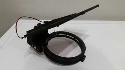
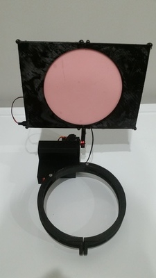
My intent was to utilize an electroluminescent (EL) panel that could have its brightness controlled remotely, and a servo to open and close the panel. However, I didn't just want the panel to move a total of 90 degrees. Even though the observatory contains seven-foot walls, I was concerned that if the panel only opened 90 degrees and was hanging out in front of the scope, a slight breeze or gust-of-wind may catch the panel, making it act as a sail and ruin my long exposures. Now I'm not going to image if it's really windy, but I'll take the nights I can get, and at the minimum, I don't want a single gust of wind to ruin an image if possible. To combat this, I devised a plan to incorporate a servo that would travel 270 degrees and lay flat against the dew shield.
Getting started:
Knowing what I wanted to incorporate, I started by purchasing an EL Panel and a servo that rotates 270 degrees. In the meantime, I took my imagination to the computer and began to 3D CAD how I thought I might lay out the design. As the parts came in, I tested their capabilities to determine what obstacles I would be facing. The first thing I received was the EL Panel, which I connected to a variable voltage supply and found I was able to operate the panel between 1 and 12 volts. This was very promising, and with time, I'll know exactly what the lowest voltage I need is, but I knew this was good for now. The servo came in later, but after a short test period, it became clear that it did not move the full 270 degrees. It did move almost the whole limit, but wouldn't have laid flat, so I sent it back and moved onto plan B, purchasing a 360 degree or continuous rotation servo. The catch going this route was I now had to find a way to stop the servo once it reached my open and close positions.
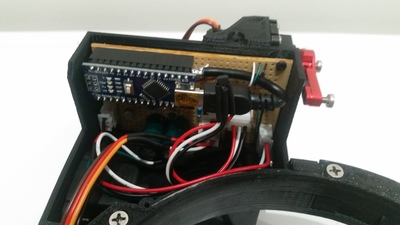
By this time, the basic design was drawn, and while I waited for the new servo to arrive, I contemplated how to stop the servo. Since the motor's speed is controllable, I was left two options, either A, stop the motor after X amount of time, or B use a switch. I settled on option B, using two hall sensors, and with this, in mind, I stepped back to my drawing and created a couple of nooks for the sensors. The other thing that required early attention was deciding how to control the brightness of the EL panel. Originally, I could use a second servo to adjust a potentiometer, but I didn't want the additional weight or to need another servo. Instead, I made the smart decision and reached out to my Dad to employ his amazing electrical engineering skills, and after explaining the design, my needs, and a few days, he got back to me with a design. He would propose to use the PWM (pulse-width modulation) of an Arduino and incorporate a couple of capacitors, resistors, and a low dropout positive regulator to smooth the signal and prevent light oscillation. After some virtual testing, a schematic was drawn up; it incorporated all the necessary components that were then transferred to a breadboard to actual testing.
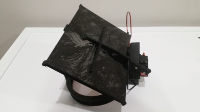
After thinking of a name, I've aptly named this the DarkLight Cover. Not only does this cover the front of the scope, but with the EL panel, I can take my dark, flats, and bias calibration frames.
Here is a video of the movement.
If you're interested in building your own, never fear as I have taken the liberty to upload the project. It's available here on my GitHub page, to get all the necessary information, software, and files to make your own, ASCOM compliant Darklight Cover Calibrator.